Web Equipment, Officers, Model of 1910
Components & Data
 With the probable exception of "J", the brass fittings were all existing standard M.E. Co. products - which would become the key to all Mills designs - never unnecessarily inventing a new wheel, when the old one would serve! The "hanger hook" was a Patent of their parent company, the Mills Woven Cartridge Belt Company, of Worcester, Massachusetts and was already in use on the U.S. Infantry Equipment, Model of 1910, usually rendered as M-1910. On two of the envelopes, the standard brass wire "C" clips have been exchanged for "C" clips made from brass strip, rivetted to the back of the envelope. This form of belt attachment has been noted on a Mills Cartridge carrier. The Belt and Braces were standard Patt. '08 W.E. , indeed the Belt would be reincarnated as the Belt, waist, special, with few changes, to be used in conjunction with Mills' later Attachments, brace, introduced by LoC No. 16513, approved 5th March 1913, to create a pistol set for Patt. '08 W.E.. The special-to-type envelopes would have been simple enough to manufacture, simply as an exercise in demonstrating Mills' weaving versatility. Mills were only in the fifth year of their existence as an English Limited Company. They were nothing if not persistent, in finding outlets for their products, which were evolving at an incredible rate during 1906-14, as witness the Cavalry Patterns of 1912 and 1913 and Pattern 1913 W.E.. The various webbings entailed were also all of stock widths.
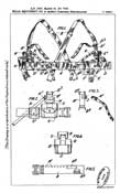
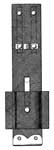
 The Patent refers to this as “…short brace extensions…”, but later as “…sling-extension member…”. This was the first outing for an item which, in a different form, would be termed a Brace attachment. In form it is the rear extension tab from a Patt. ’08 belt, complete with gated 2-inch buckle, but with an inverted, U.S. style hanger hook stitched to the lower end and of original form, i.e. a pair of simple hooks, without the later horizontal bends of the standard U.S. and Patt. ’44 form. The attachments are “handed”, since a web chape is stitched to the rear face, on the outside vertical edges. The chape holds a brass loop of rounded triangular form, providing a downward inclination for the equivalent of the diagonal straps of Patt. ’08 Cartridge carriers. As with the Cartridge carriers, the 2-inch buckle was arranged to face inwards to the wearer, the gate pointing downwards.
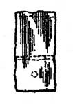
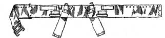 This was the standard Patt. ’08 Belt, waist, to which long loops, in ¾-inch webbing, were stitched, along the upper edge. Their rearward ends were about 2-inches away from buckles on chapes, without the extension tabs of the ’08 Belt. Stepped slightly rearwards, from the end of the web loops, a narrow, brass wire loop was attached by a chape. This had a 2-inch strap accommodation. Around 9 eyelets were inserted along the top edges of the belt, at 1-inch pitch and providing anchorage for the Brace attachment hooks.
Pouch, binocular, with ammunition carrier
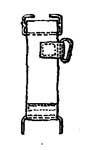
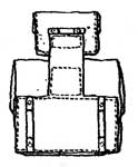 The Patent drawing is impractical, showing an un-likely, sharp cornered, inverted “T” shape – one piece. At this stage, Mills had not developed reduction weaving, so the “T” would have been assembled from a rectangular section of belt width webbing. To this, a 2-inch wide vertical extension was attached. The cross-bar of the “T” then formed the backing piece for the Binocular case, which may have been an integrally woven item, but was more probably an assembly, comprising a horizontal “loop”, forming front, back and sides, into which a base piece was stitched. A flap was then stitched to this, closed by a single press-stud. On the upright of the “T”, stitched above and clear of the Binocular case, there was a small pouch, specifically stated as being for ammunition. This was broader than it was high, closed by a simple flap and one press-stud. Again this may have been integrally woven, or assembled from pieces. At the top of the vertical of the “T”, a “C” hook in flat brass strip was riveted horizontally. On the back of the Binocular case, at the outer edges, “C” hooks of 3-inch strap accommodation were riveted in place.
 This was a shorter Patt. ’08 style of Frog, described in the patent as having “…a shorter neck… “, to raise the sword higher. The scabbard loop was a single piece of webbing, into which a pillar stud was rivetted. The tab of the leather Sam Browne scabbard fastened over the stud.
 This is included, as its Patent date precedes the trials, so Mills may have used this superior form, to showcase their latest design. For the first time Mills were clearly referring to a Sam Browne Frog, though the name did not feature! It replicated “Hooking up” in a most ingenious manner.
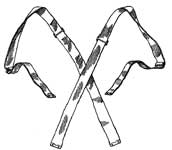
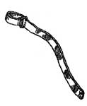
Two pieces of 2-inch webbing, approximately 9-inches long, were sandwiched at their lower ends with a Tip, brass, 2-in. The cross-section clearly shows two pieces, yet there is no turn-back to protect the cut ends, which would not be Mills’ practice. It is more likely it is one piece, 18-inches long and folded in half. A sleeve formed by two pieces of 2.5-inch webbing, stitched together, was placed over the front section of the folded webbing, where its stitched edges protruded beyond the body strap. The scabbard loop was formed with a third piece stitched to the front of the sleeve, with a pillar stud for the scabbard tab of a Sam Browne Scabbard. The sleeve was free to slide vertically and a brass strip was riveted inside, on the top front section and was formed into a hook, pointing inwards. Although the Patent illustration was finely drawn, the sleeve could not be made as shown. Either it would need to have been folded, with the opposite ends turned in and stitched or, if in two pieces, the cut ends of both sides would need turning-in.
The same flat strip “C” hooks were riveted to the rear face of the body, with a transverse strip on the front face and secured by the lower pair of “C” clip rivets. The short strip was formed into a standing loop, on which the sleeve hook could be engaged, when “Hooking up”.
Mills were constantly striving to find new applications for webbing, but on several occasions their solutions were hugely over-engineered. As they progressed up the learning curve, developing new fittings and techniques, their designs were simplified. This frog is an example of this over-engineering, Mills having thought a little too far “outside the box”. It is therefore interesting to note their original premise – to improve on the (un-named) Sam Browne Frog. After the Great War, their 1919 modification of the Web Equipment for Officers, included a new Frog – constructed exactly as a Sam Browne Frog, but in webbing.
Holster, pistol, with ammunition carrier
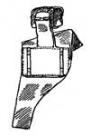 Constructed on “T” backing piece, as with the Binocular case, the curved form illustrated shows it was not integrally woven, a technique evolved only later. Instead, it was cut from webbing, folded and stitched. Above and clear of the Holster, an Ammunition pouch was stitched in place, corresponding to that on the Binocular case. The same arrangement of transverse “C” hook and larger “C” hooks, for attachment to the Belt, were riveted in place. The Holster flap is shown extending out on the butt side, suggesting it was straight-sided extension of the back wall, with an off-set press stud to angle the flap over the pistol butt.
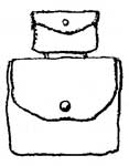
 Simply termed “…an additional pocket…”, this was slightly taller than the belt width and a little over half the width of the Binocular case. Whether integrally woven or a stitched assembly is not clear, but it was fitted with a simple flap, closed with a single press-stud. Flat brass strip “C” hooks were riveted to the rear, for attachment to the Belt. It was specifically stated to be for “…a compass, spare ammunition, first aid packet, or the like…” which, in modern parlance would make it a Utility pouch.
 Termed a “…rearwardly extending strip…”, the nomenclature above is the later nomenclature for this component. These were short, 1-inch straps, fitted at one end with a brass loop. The Strap was passed through the angled loop on the Brace attachment, then through its own loop. Thus fixed, it formed the diagonal strap equating to that of the Patt. ’08 Cartridge carrier. With the Brace attachment in position, the Strap was threaded through the long inside web loop of the Belt. It then passed through the narrow brass loop, where a turn was taken around the loop to fix it in position. A Pack, or Greatcoat carrier could be attached to the diagonal straps and sliding Brace buckles, exactly as with Patt. ’08.
Rog Dennis, July 2010